
Injection Molding Process: The Five Phases and How to Control Them
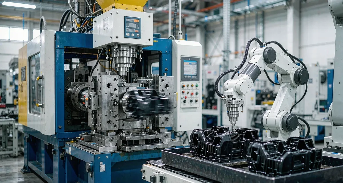
Every injection molded part ever made has been made the same way: the mold closes and locks, the screw pushes molten resin into the cavity, added pressure holds the melt against shrinkage while the part cools, and ejectors release it. Five phases, every shot, from a bottle cap to a battery housing. Most of what separates a good tool from a problematic one is not the geometry and not the steel — it is how well those five phases are understood and controlled. This guide walks through each phase, shows where a cycle actually goes, explains what a process window is and why it is the whole game, and gives the order in which parameters should be changed when something goes wrong. If you are trying to cut cycle time, choose a machine, or diagnose a recurring defect, the answer is almost always in one of these phases.
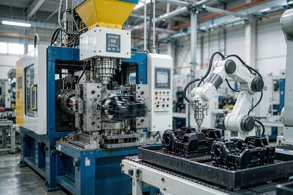
The five phases of every moulding cycle
The injection molding process is clamping, injection, packing, cooling and ejection, and they run in that order on every single shot. Between 95 and 98 percent of the part is formed during the fill phase alone, which means that almost every quality problem is decided in the first two phases and only becomes visible during cooling or ejection. Cooling normally accounts for 30 to 50 percent of the cycle, which makes cooling design — not machine speed — the main determinant of achievable cycle time. And the reason production molding is repeatable rather than a matter of operator skill is the process window: a range of pressures, temperatures and speeds within which the part is consistently good, established at trial and then frozen into documented setpoints.
Two practical rules follow from that, and they are the reason this guide is worth reading in full. First, the process is a system, and the fastest way to fix a problem is to change one variable at a time in the correct order — the order is in the parameter section below, and jumping straight to the mould temperature destroys more tools’ time than any other habit. Second, a tool is only as good as the records that came with it: the frozen parameter set, the first-article dimensional report, the cavity balance and the material specification. A mould without those is not a mould you can defend, and it is not a mould you can hand to a second molder.
Our injection molding service page covers the equipment behind these phases, the injection molding process overview covers the same ground at pillar-page depth, and the mold flow analysis page covers what simulation predicts before a single shot is run.
The five phases of every shot
It is worth being precise about the phases, because most shop-floor language conflates them and the confusion shows up in the parameter sheet.
1. Clamping
The mold closes and the press locks it against the injection force. This is where the projected area of the part matters, because the force the clamp must resist is the force the injection unit generates. A tool with a large projected area needs proportionally more clamping force, and a tool with a deep core or a long flow path needs more than its area alone suggests. Clamping also positions the core: it is what defines the parting line and therefore what determines flash.
2. Injection (fill)
The screw rotates and pushes molten resin through the sprue, the runner and the gate into the cavity. This takes anywhere from a fraction of a second to a couple of seconds depending on the flow path, and it is where 95 to 98 percent of the part is formed. The key insight for troubleshooting is that fill is governed by flow resistance, which is a function of temperature, speed and geometry — not by a single machine setting you can dial in isolation.
3. Packing (hold)
Once the cavity is full, a holding pressure is applied to the melt to compensate for shrinkage as the material cools. This is the phase that decides sink marks, voiding and flash. Holding too little gives you sink; holding too much or too long gives you stress, flash, and cycle time you did not need to spend. Hold time is commonly set at roughly half the fill time and then adjusted from there.
4. Cooling
The part solidifies while it is still clamped to the core. Chilled water or oil circulating through the cooling channels removes the heat, and the mold temperature setpoint around the cavity decides both the cooling rate and how much the part shrinks. This is normally the longest phase and the one with the most design headroom.
5. Ejection
The mold opens and ejector pins, an ejector plate or a stripper plate pushes the part off the core. This is where undercuts get their attention, where the ejection force has to be checked against the material’s stiffness, and where a poorly balanced tool produces a part that is slightly out of shape. Ejector pin marks on a cosmetic surface are a design decision, not a supplier error, unless nobody told you they were there.
The useful mental model is that the first three phases determine whether the part is correct, and the last two determine whether you can make it fast and get it out of the mold without damage. Our injection molding defects reference covers what each phase produces when it goes wrong.
Where a cycle actually goes
The single most useful diagnostic exercise in injection molding is taking one cycle apart and accounting for every second. Typical production cycles fall between 10 and 60 seconds, and the breakdown is remarkably consistent across tools.
| Cycle component | Typical range | What it is controlled by |
|---|---|---|
| Plasticising and screw recovery | 1 to 3 s | Resin bulk density, screw diameter, back pressure; rarely the bottleneck |
| Fill (injection) | 0.3 to 2 s | Flow resistance, temperature, speed, gate and runner design |
| Pack (hold) | 0.5 to 3 s | Hold time and pressure; set relative to fill time |
| Cooling | 5 to 25 s | Wall thickness, channel design, mould temperature, material |
| Ejection and handling | 1 to 6 s | Ejector speed, robot pick path, takeout time |
| Open time and closing | 1 to 4 s | Platen parallelism, guard and safety-door timing |
Read that table with one question in mind — where does the money go? On most tools cooling is 30 to 50 percent of the cycle, sometimes more on thick parts. That is why the levers that actually reduce cycle time are cooling channel design, mould temperature, and removing unnecessary mass from the part and the runner, in that order. Raising screw speed changes the 1 to 3 seconds of recovery and nothing else. A tool that is cooling-limited does not become faster by injecting faster, and a lot of cycle time projects have been lost to that misunderstanding.
There is a second, less obvious reason to care about cycle time breakdown: the same part at the same cycle can be cheap at 100,000 pieces a year and uneconomic at 5,000. The machine-hour cost is only part of it — cycle time drives how many parts a press produces, how many presses you need, and whether the tool pays back its own cost at the volume you actually have. Our mold cost breakdown works through that arithmetic with real figures, and the lead time guide covers how cycle time and setup time combine into a schedule you can promise.
What a process window is, and why it is the whole game
A process window is the range of pressure, temperature and speed within which a part comes out consistently good. Its existence is the entire reason production molding is repeatable rather than a matter of who is running the press.
The practical consequence is that a tool does not have “correct settings” so much as it has a window, and your job as an engineer is to find the middle of that window and then write it down. The window is established during trial, confirmed across resin lots and ambient conditions, and then locked in as a parameter sheet. That sheet is why the shift running week two produces the same part as the shift that approved first article.
Windows vary enormously in width, and the width is a design outcome as much as a process outcome. A tool with good venting, balanced filling, consistent cooling and a well-conditioned resin has a wide window: it tolerates a resin lot change, a temperature drift and wear for a long time. A tool with a hot spot, a poor gate location and one cavity running hot has a narrow window: it goes out of specification when the ambient temperature changes in the afternoon, and every out-of-spec part is a credit, a scrap or a rework.
This is also the practical meaning of “scientific molding” — the term is used loosely, but the idea is specific. You identify the window, you sit in the middle of it rather than at its edge, and you document the setpoints. Running at the edge of a window is what produces the mysterious shift-to-shift variation that gets blamed on the operator. Our quality and certification page covers the inspection regime behind every batch, and the process overview covers the trial sequence in more detail.
Fill and pack: 95 percent of the part, and most of the problems
Fill is the phase that forms the part, and it is where material temperature, mould temperature and injection speed combine to decide whether the flow front arrives evenly or whether you get weld lines, jetting, burn marks and short shots.
Three variables move fill, and they interact:
- Material temperature — higher reduces viscosity, so the flow front moves further per unit of pressure and the pressure needed drops. Too high and you get flash and a longer cycle because you have to wait for the material to cool.
- Mould temperature — this sets the cooling rate from the moment the resin touches the wall. A cold mould gives you short shots and weld lines from a frozen skin; a hot mould gives you flash, long cycles and sink because the part shrinks more before it is released.
- Injection speed — faster fill reduces the frozen skin depth but raises the pressure the clamp has to hold, so it moves the flash threshold down.
Pack then decides what happens to the material that is already in the cavity. Because the melt is still hot and still trying to shrink, added pressure is required to push material into the skin that formed during fill. Under-packing gives you sink marks over thick sections and voids at gate-adjacent thick walls. Over-packing gives you excessive residual stress, which shows up later as stress cracking or a part that warps out of shape after ejection, and flash that you do not need.
| Material | Typical total shrinkage | Note for tool compensation |
|---|---|---|
| PET | about 0.3 to 0.5 % | Low shrinkage; crystallisation makes it sensitive to cooling rate |
| Clear ABS / ABS | about 0.4 to 0.7 % | Good dimensional stability; the usual choice for housings |
| Polycarbonate | about 0.5 to 0.7 % | High melt strength, so flow is stable but pressure is high |
| Glass-filled nylon (PA6 GF) | about 0.3 to 0.6 % | Low shrinkage but highly anisotropic — flow direction matters |
| Polypropylene | about 1.0 to 2.5 % | High shrinkage and it shrinks unevenly; most sink risk |
| POM | about 1.8 to 2.0 % | Highest shrinkage of the common engineering grades; tool compensation needed |
Note the last column rather than the numbers alone. Datasheet shrinkage is a starting point for the tool, but the actual shrinkage of your part depends on how well it was packed, what the packing history was, and how it was cooled. Two parts of the same material from two different tools do not shrink the same amount, and that is why a compensation figure copied from a handbook is a starting point and not an answer. The mold design guide covers how that compensation is built into the tool.
Cooling: the phase that sets your cycle time
Cooling is where cycle time is won or lost, and it is also the phase that decides dimensional accuracy, because a part that is ejected before it has released its heat will distort on the way out of the tool.
Cooling time is a function of wall thickness and of the thermal resistance between the melt and the coolant. The practical relationships are well behaved enough to design with:
- Cooling time scales with the square of wall thickness. Doubling wall thickness roughly quadruples the cooling time, which is why “make it stronger” is rarely free.
- Cooling time scales with the cube of the resin’s thermal diffusivity in the other direction: a lower-diffusivity resin such as POM or a filled grade cools far more slowly than the numbers on a data sheet suggest.
- Channel placement matters more than channel volume. A channel that runs beside the thick section and not through it cools the thick section no better than no channel at all.
- Mould temperature setpoint is often worth more than any channel change, because it moves the whole curve rather than one region.
There is a design consequence here that is often missed: the thickest section on the part is usually the thing that sets the cycle time, and it is often also the thing that causes sink. A part with a ” rib where you do not need one” is not just heavier and slower, it is the source of the sink mark that then gets “fixed” by over-packing, which shortens the cycle again in the wrong direction. Our mold flow analysis page covers how simulation predicts these thick spots before the steel is cut, and the mold design checklist lists the design rules that prevent them.
Clamping force and how to size it
Clamping force is the number everyone wants a rule of thumb for, and the honest answer is that the rule of thumb is only a starting point.
The clamp has to hold the mold closed against the force the injection unit generates at the parting line. A practical starting estimate for ordinary thermoplastics is 2 to 4 tons of clamping force per square inch of projected part area, rising substantially for long-flow, high-viscosity or glass-filled grades. Multiply by the projected area — the outline of the part as seen from above, including anything that sticks up — and that gives you a tonnage figure to start a conversation with.
The variable that gets missed is not the area, it is the flow. A part with a deep core, a long runner, a thick section or a high-viscosity resin needs more force than its projected area suggests, because the injection pressure required to fill it is higher. The correct final figure is set by the pressure needed to fill the cavity against that flow restriction, and it is confirmed at trial. If you are short of clamping force you get flash; if you are far over it, you are paying for a bigger machine than you need and paying for the energy to hold it there.
| Projected part area | Typical machine class | Typical part |
|---|---|---|
| under 10 in² (65 cm²) | 40 to 100 ton | Small housings, caps, connectors, medical components |
| 10 to 40 in² (65 to 260 cm²) | 100 to 250 ton | Appliance parts, ducting, larger consumer housings |
| 40 to 120 in² (260 to 775 cm²) | 250 to 500 ton | Structural housings, automotive interior parts |
| over 120 in² (775 cm²) | 500 to 1,800 ton | Large panels, structural automotive and energy-storage parts |
Our shop floor runs presses from 50 to 1,800 tonnes in automated cells with robotic takeout, which is what the factory page covers. One thing worth noting for buyers: the machine tonnage you are quoted is not the same thing as the machine size that matters. A 300-ton press with a small screw can be slower and more marginal for a thin-wall part than a 200-ton press with a large screw, because the screw governs plasticising rate and therefore how many parts per hour you get out of the clamp. Our turnkey solutions page covers running the whole route — design, tool, production, inspection — as one project.
Choosing a machine: tonnage, screw and the rest
Machine selection is a trade between three things, and buyers usually optimise the wrong one first.
Tonnage you have covered above. Screw diameter is the one that catches people out, because it determines plasticising rate: a larger screw recovers more material per second, and if your cycle has a short recovery phase and a long cooling phase, the screw that matches your cycle is the one that finishes recovery before cooling ends. Platen size and tie-bar spacing determine whether your mold physically fits, and they are a hard constraint rather than a preference. Injection unit size determines how much material is available per shot, and you want it sized so the shot is not more than about 80 percent of the machine’s capacity — over-sizing causes long recovery and wasted resin in the barrel.
Two further points matter more in practice than the spec sheet suggests. The first is injection speed and response, because the difference between a machine that can deliver a set fill time and one that cannot is the difference between holding a process window and losing it. The second is how the cell is laid out: robot takeout, conveyance and part sensing determine how much of the cooling phase you can actually use productively. A press that has to wait for an operator to take the part out is not a 12-second cycle tool no matter what the catalogue says. Our automotive molding and industrial molding pages show how these cells are configured for high-volume programmes.
When something goes wrong: the order to change things in
This is the part of the process that most people get wrong, and getting it wrong is expensive, because changing several variables at once means you never learn which one mattered — and you may have made the problem worse while making it more expensive.
Change one variable at a time, and change them in this order:
- Mould temperature first. It is the strongest single lever on fill, on shrinkage and on cycle time, and it is the safest to change because it does not create flash on its own.
- Material temperature second. Lowering it increases flow resistance and pressure; raising it reduces pressure but costs cycle time in cooling.
- Injection speed third. Adjust it when you are chasing a weld line or a jetting mark, and keep the rest of the process fixed while you do.
- Packing pressure fourth. Increase it in small steps when you are chasing sink; stop as soon as the sink goes, because excess hold causes stress and flash.
- Hold time last. It is usually set at about half the fill time and adjusted from there.
The order reflects a simple principle: change the variables that affect flow before the variables that affect how much material stays in the part. Flow problems show up as fill defects; material problems show up as shrinkage and stress. Mixing the two means you chase a sink mark by changing speed and never find the cause.
One more rule that is worth more than any of the above: before changing any parameter, confirm the tool is not the problem. Check cavity pressure, check venting, check gate condition, check for wear. A parameter change made on a degraded tool hides the degradation instead of fixing it, and the problem returns worse a few weeks later.
Telling a tool problem from a process problem
There is a diagnostic shortcut that works remarkably often, and it costs nothing but a little discipline.
If the same defect appears on every cavity and moves with the tool when it is transferred to another press, it is a tool problem — geometry, cooling, gating or venting. If the defect appears and disappears within a shift at constant settings, it is a process or material problem — a resin lot, a feed problem, moisture in hygroscopic grades, or a barrel temperature that has drifted. If the defect appears on one cavity only and gets worse over time, it is wear, and the answer is preventive maintenance, not a parameter change.
| Symptom | Most likely phase | First thing to check |
|---|---|---|
| Short shot | Fill | Vent at the end of flow, then mould temperature and speed |
| Weld line | Fill | Gate position relative to the weld, then melt temperature |
| Flash | Fill / clamping | Clamping force and parting line condition, before anything else |
| Sink mark | Pack / cooling | Packing pressure and hold time, then the thick section itself |
| Void | Pack | Hold pressure and gate placement relative to the thick wall |
| Jetting or burn mark | Fill | Gate entry and melt temperature at the gate |
| Warpage after ejection | Cooling / ejection | Ejection temperature and unbalanced cooling |
| Short shot life | Wear | Gate wear and vent fouling, not settings |
Our injection molding defects reference goes through each defect in detail with the geometry and the material causes for it, and the mold maintenance page covers the preventive schedule that stops the wear column in that table from ever becoming a problem in the first place.
Three process decisions
A process window is not something you look up — it is something you find. These three are real decisions from our own production work, and in each case the answer that seemed obvious at the start was wrong, because the process was being blamed for a tool problem, or a tool was being blamed for a material problem.
Case 1: The flash that was not a clamping problem
An appliance customer reported intermittent flash on a large housing, seen on roughly one shot in forty and never on the first two hours of a shift. The obvious reading was insufficient clamping force, and the obvious fix was to move the tool to a bigger press.
Before doing that, we measured cavity pressure. It was healthy — the problem was that the flash was not at the parting line at all. It was at the ejector pin holes, and it was caused by a vent that had been blocked by a slug of regrind that had sat in the vent pocket and slowly worked its way down into the throat. It was visible only intermittently because the slug moved. The general lesson is that flash has more than one cause, and the cheapest diagnostic is to look at where the flash is before deciding what it means. Moving to a bigger press would have cost more money and hidden the actual defect, and the flash would have come back as a worn vent a few weeks later.
Case 2: The sink mark that was really a design decision
A medical device customer had a part with a persistent sink mark over a boss 4 mm thick, and asked us to raise the packing pressure to remove it. Raising pressure did reduce the sink, and also introduced stress cracking in a transparent housing that had to be sterilised after moulding.
The real cause was that the boss was thick because the assembly needed a screw boss there, and the boss did not need to be 4 mm — it needed to be 2.5 mm with a steel insert that was already specified for the joint. We redesigned the boss around the insert, which brought the wall down to a thickness the pack could actually fill, and the sink went without touching the pack pressure at all. The general lesson is that pack pressure is the right lever for a pack problem and the wrong lever for a design problem, and because packing pressure is easy to change, it gets used to paper over geometry that should have been fixed in the design stage. Our mold flow analysis is where that thickness problem should have been caught, before the steel was cut.
Case 3: The cycle time that could not be improved on the machine
An energy-storage customer wanted 22 seconds instead of 31 on a structural housing, and the plan was to specify a faster injection unit and higher screw speed. The cycle breakdown told a different story: plasticising and recovery took 2.4 seconds, fill 1.1, pack 1.3, cooling 24, and handling 2. Cooling was 77 percent of the cycle, and the wall thickness on the largest section was 4.5 mm.
Two changes did it. The first was cooling channel design — moving the channels to sit directly under the thick section rather than beside it, and adding a second circuit for the boss — which took cooling from 24 seconds to 15. The second was a 0.6 mm reduction in wall thickness on the non-structural sections, agreed with the customer after they confirmed the stiffness requirement was met by the ribs rather than the skin. Final cycle was 19.5 seconds, and it was achieved on the same machine, with the same screw and the same clamping force. The general lesson is that a cooling-limited tool does not become faster by injecting faster, and that cycle time reduction projects are usually design projects wearing a production disguise.
Injection molding process terms quick reference
| Term | Meaning | Why it matters when running or buying a tool |
|---|---|---|
| Projected area | The outline of the part seen from above, used to size clamping force | The starting point for tonnage selection; the real requirement is usually higher because of flow |
| Clamping force | The force the press applies to hold the mold shut against injection pressure | Too little gives flash; far too much wastes machine size and energy |
| Fill time | The time taken to fill the cavity, usually a fraction of a second to a couple of seconds | Governed by flow resistance, temperature and speed — not by one setting |
| Pack (hold) time and pressure | The pressure and time applied after the cavity is full, to compensate shrinkage | Decides sink, voiding and residual stress; the most over-used lever in molding |
| Process window | The range of pressure, temperature and speed within which the part is consistently good | The reason production molding is repeatable; a narrow window makes the tool expensive to run |
| Scientific molding | Finding the window, sitting in the middle of it, and documenting the setpoints | Turns molding from an operator skill into a controlled process |
| First article | The first production part, inspected in full against the drawing | The baseline that every dispute about the part is settled against |
| T0 / T1 trial | Tool trials on the production press: T0 is the first, T1 the corrected repeat | Where the process window is found and the tool is corrected |
| Gate | The entry point where resin enters the cavity | Its position determines weld lines, jetting and how evenly the part fills |
| Hot runner | A runner system that keeps the melt hot all the way to the cavity | Removes runner scrap and cold slugging; costs more in tooling and needs control |
| Cooling channel | A passage in the tool carrying chilled water or oil | Its placement, not its volume, decides what actually cools |
| Vent | A small groove at the end of the flow path letting trapped air escape | Blocked vents cause burns and short shots that get blamed on the process |
Moulding process questions, answered
What are the five phases of the injection molding process?
How long does an injection molding cycle take?
How do you calculate the clamping force an injection mold needs?
Why does cycle time not change when you raise the screw speed?
What is a process window and why does it matter?
How much does resin shrinkage affect the part?
What is the difference between injection pressure and packing pressure?
How do you reduce injection molding cycle time?
How do I know whether a problem is the tool or the process?
What should be documented before production release?
Production moulding capacity
Send us the drawing, the resin and the volume
Share the STEP or IGS file, the material grade, the annual volume and the cycle time you need to hit. We will tell you what the process will look like on your part, where the cycle time actually goes, and what the tool will cost.
No obligation. NDA available.
- 23+ Years of experience
- 2,000+ Molds per year
- 24h Quote turnaround