
Two-Shot Injection Molding: Process, Materials and Cost Guide
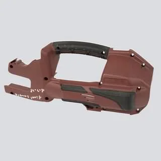
A two-shot part looks simple: a rigid plastic body with a soft
rubber-like grip over it, one component, no glue. Producing it is not simple at all.
Two-shot injection molding requires a tool that carries two cavities and rotates
between them, two injection units feeding two materials, and a bonding interface
between two polymers that shrink by different amounts. Get any of those three
things wrong and the part either delaminates, warps, or costs more than the
assembly process it was supposed to replace. This guide compares two-shot molding
against overmolding, insert molding and adhesive assembly on cycle time, cost and
failure modes, and explains how to decide whether it is the right process for
your part before you commit to tooling.
Short answer
Two-shot injection molding produces a two-material part in a single machine
cycle: a rigid substrate is moulded first, the tool indexes 180 degrees on a rotary
table, and a soft material such as a TPE, TPU or liquid silicone is moulded
directly over it, bonding as it cools. There is no glue and no separate assembly
step.
Choose it when the part needs a soft-touch surface, a grip, a sealing lip or
an elastomeric overmould, and when the volume is high enough for the tooling
premium to pay for itself. Expect a tool cost roughly 50 to 150 percent above a
comparable single-shot tool, offset by the elimination of a second component, an
adhesive and a labour step.
Choose overmolding instead when the substrate comes from a supplier, the
volume is low, or the two materials cannot be processed in the same cycle. Choose
insert molding when what you need is a threaded insert or a metal contact, not a
soft surface. And choose plain single-shot molding when the part does not need a
soft region at all — which is more often than the process is sold.
Two-shot, overmolding, insert molding and glue
These four routes all end up with a plastic part in the hand. They differ in
what they cost, how long they take per part, and how they fail. The table below
is the comparison we walk through with buyers at quotation stage.
| Factor | Two-shot (2K) | Overmolding | Insert molding | Glue or snap assembly |
|---|---|---|---|---|
| Cycles per part | 1 shot + indexing, typically 3 to 8 s added | 2 full shots + transfer and load time | 1 shot, plus insert loading time | 2+ separate operations |
| Tools required | 1, with two cavities and a rotary mechanism | 2, on two machines | 1, with insert pockets | 1 per component |
| Tool cost vs single-shot | Typically +50 to +150 percent | Two tool costs, roughly 2x combined | Modest premium for insert pockets | Two tool costs |
| Component count | 1 | 2 | 1 plus the insert | 2 or more |
| Bond or joint | Chemical, formed in-cycle | Chemical, formed in the second tool | Mechanical, via knurl or undercut | Adhesive or mechanical |
| Main failure mode | Delamination and interface warpage | Same as two-shot, plus transfer damage | Insert loosening or pull-out | Adhesive ageing, joint fatigue |
| Typical annual volume where it wins | Above roughly 50,000 parts | Below roughly 50,000 parts | Any volume, driven by the feature | Low volume prototypes |
Two things in that table deserve emphasis because they are where quotes go
wrong most often.
The threshold is about volume, not part complexity. Buyers
often expect two-shot to win because it is a “better” process. It is a better
process for the right volume. Below roughly 50,000 parts a year, the rotary
table’s capital cost and its machining time are not amortised, and a two-shot
tool costs more than the two tools and labour it replaces. Above that, the
opposite is true, and the gap widens.
Insert molding is not a cheap version of two-shot. An insert
tool has no second injection unit and no rotary table, so it is genuinely
cheaper — but it does something different. It embeds a threaded insert or a metal
contact so that the part can be screwed together or carry current. If your
requirement is a soft-touch grip, an insert tool will not deliver it, and if
your requirement is a thread, a two-shot tool will not deliver it either.
How a two-shot tool actually works
The mechanical difference between a two-shot tool and a normal tool is a
rotary table, sometimes called an index table, that sits between the two
injection units. The tool opens, the first unit injects the rigid substrate into
cavity one, and while that part is still hot the table rotates 180 degrees. The
second unit then injects the soft material into cavity two, directly over the
substrate, and the two bond as the soft material cools against the substrate
surface.
Two consequences follow from that mechanism and they shape the whole
design.
Nothing leaves the machine. The substrate is never demoulded,
never transferred, never handled. That is what keeps the cycle penalty down to
single-digit seconds instead of a whole second cycle, and it is also why the
bond is reliable: the substrate surface is still warm and clean when the soft
material arrives, with no handling in between to contaminate it or scratch it.
The second shot must be able to release from the first. This
is the constraint that surprises people most. After the first shot, the
substrate is still sitting in cavity one, and the soft material is moulded
around it in cavity two. The substrate has to release from cavity one cleanly
while under the pressure of the second shot. Any feature without adequate draft
will drag, and a dragged substrate is a scrapped part and potentially a damaged
cavity. Draft angles that would be marginal in single-shot molding are simply
not enough in two-shot.
| Step | What happens | What can go wrong |
|---|---|---|
| 1. First shot | Rigid substrate moulded in cavity one, typically PP, ABS or PC/ABS | Under-packed part leaves voids; too hot a substrate warps later |
| 2. Index | Rotary table rotates 180 degrees, carrying the hot substrate to cavity two | Index timing tied to the press cycle; a mis-set sensor scrapes parts |
| 3. Second shot | Soft material moulded over the substrate and bonds as it cools | Delamination if the surface is contaminated or the melt is too cold to wet it |
| 4. Cooling | Soft layer must cool enough to be demoulded without distortion | Under-cooling causes a soft grip that twists or shows a witness mark on the next part |
| 5. Ejection | Part ejected with the overmoulded grip intact | Ejector marks on the soft surface; grip tearing at corners |
There is one more practical consequence of indexing: the tool has to run two
machines’ worth of injection on one base. The rotary table makes the machine
footprint larger than a single-shot tool of the same clamping force, and the
injection units have to be sized so that both shots are properly plasticised
before the index. A tool designed for a 350 g soft layer and a 250 g substrate
cannot simply be run with the same settings as a 250 g part; the barrel has to
hold both shots’ worth of melt at the right temperature.
Material pairs that bond, and pairs that fight
The bonding in a two-shot tool is chemical, not mechanical. The molten soft
material has to wet the substrate surface and form a real interface with it,
rather than sitting on top like paint. That is why the choice of pair is an
engineering decision and not a purchasing one, and it is why the surface
condition of the substrate matters as much as the chemistry.
| Substrate | Typical soft material | How it behaves | Notes |
|---|---|---|---|
| Polypropylene (PP) | TPE-S, TPE-V, TPV | Excellent bond, low cost, forgiving window | The most common combination in the industry for a reason |
| ABS / AS | TPE, TPU | Good bond with correct melt temperature | Watch for chemical stress cracking if a PC/ABS blend is used |
| PC/ABS | TPE, TPU, liquid silicone | Good bond; needs care on the soft material’s temperature | Common in consumer electronics and medical housings |
| Polyamide (PA6, PA66) | TPE, TPU | Good bond, good wear and temperature performance | Used where the part sees heat, chemicals or wear |
| POM | TPE | Workable but the soft material must stay below the substrate’s softening point | Limited window, worth discussing early |
| Polycarbonate (PC) | Liquid silicone, TPE | Difficult: the soft material’s melt is close to PC’s softening point | Feasible but the process window is narrow |
| PVC | TPE, TPU | Difficult, and corrosive to tooling over time | Requires corrosion-resistant cavity steel |
Two failure patterns recur, and both are worth understanding before you
specify a material pair.
Shrink mismatch. The rigid substrate and the soft elastomer
shrink by different amounts during cooling, and the soft material contracts
more because it is a rubber. That difference puts the interface into peel
stress. It shows up as a lifting edge at the perimeter of the grip, or as a
part that is flat when it comes out of the tool and curved a day later. This
is not a bonding failure — the chemistry was fine — it is a stress problem, and
no adhesive would have saved it.
Contamination. Any release agent, oil, dust or moisture on
the substrate surface prevents wetting, and the result is a clean-looking part
that delaminates in the customer’s hands two weeks later. In a two-shot tool
the substrate surface is moulded in the same tool moments earlier, so it is
protected — but only if the cavity is kept clean. This is a maintenance
discipline issue rather than a design one, and it is one of the reasons the
moulding tool in your hands and the injection moulding tool that made it are
often the same supplier.
The four failure modes
Almost every two-shot problem that reaches a troubleshooting discussion is one
of four things. Knowing which one you have saves the days that get spent
changing process settings that were never the problem.
1. Delamination — the interface peels
Symptoms: the soft layer lifts at an edge, or separates cleanly along a
moulding line, or comes away in the customer’s hands after weeks of service.
Causes in order of likelihood: contaminated substrate surface, incompatible
material pair, soft material melt temperature too low to wet the substrate, or
shrink stress concentrating at a sharp corner. Diagnosis starts by looking at
where the peel begins — at a corner points to geometry, along a whole line
points to surface condition, everywhere points to chemistry.
2. Warpage — the part curves after moulding
Symptoms: the part is flat at ejection and bows by morning, or it will not
sit flat on a fixture. Cause: asymmetric shrink stress from the soft layer, or
uneven cooling because the soft material’s insulation is different from the
substrate’s. This is the failure mode most often misdiagnosed as a material
problem when it is really a geometry problem — the soft layer covers one side
of the part, and one side shrinking more than the other will bow it.
3. Insert or feature failure — the part separates
Symptoms: a threaded insert spins, a metal contact pulls out, a grip detaches
at a knurl. Causes: insufficient plastic thickness around the feature,
insufficient mechanical retention for the load, or an insert that was moulded
in at a temperature its adhesive cannot survive. If the feature is a thread
rather than a soft surface, this is an insert-moulding problem wearing a
two-shot hat.
4. Cosmetic — the part is right but ugly
Symptoms: witness marks, flash on the soft face, mould texture showing
through a thin soft layer, ejector pin marks in the grip. Causes: cooling time
tuned for the substrate rather than the soft material, a parting line crossing
the visible face, or a soft layer below about 1.5 mm. These are the cheapest
problems to fix and the most common in first-article parts, because they are
process-window problems rather than design problems.
Design rules that decide whether it works
Every one of the four failure modes above traces back to something that was
decidable on the 3D file before the tool was quoted. This is the section we use
in our own DFM review, and it is worth running against your drawing before
requesting a quotation rather than after the first shot.
| Design rule | Recommended | Why it matters |
|---|---|---|
| Draft on all substrate surfaces the second shot wraps | 1.5 to 2 degrees minimum; never below 1 degree | The substrate must release from cavity one under second-shot pressure |
| Internal corner radius under the soft material | 1 mm or greater; 2 mm on cosmetic parts | Sharp corners concentrate shrink stress and start the peel |
| Soft layer thickness | 1.5 to 3 mm | Below 1.5 mm the substrate texture shows through; above 3 mm sink and stress rise |
| Parting line placement | Never across the visible soft face | TPE flash cannot be trimmed from a soft-touch surface without a witness line |
| Plastic around threaded inserts | 1.5 to 2 mm of radial wall, plus a knurl or undercut | Below this the insert strips under real torque, not hand torque |
| Unsupported soft overhangs | Keep overhangs short or add a rib beneath | Undersized overhangs sag and read as a defect to the end customer |
| Ejection | Eject from the substrate side, never the soft face | Ejector pins leave marks in a soft surface that cannot be polished out |
| Surface texture of the substrate | Fine texture, SPI B30 or better | A coarse cavity texture prints through the soft layer |
Two of these deserve a note because they are the ones that get ignored.
Draft is not a cosmetic rule in two-shot molding. In
single-shot molding, marginal draft may cost you a little scrap. In a two-shot
tool it can cost you the cavity, because the dragged substrate is a symptom of
a tool that is being damaged on every cycle rather than a part that failed once.
When we review a two-shot drawing, draft on the substrate is the first thing we
check and the thing we most often have to raise with the customer.
The parting line cannot be moved after the fact. Once the
tool is built, the parting line is where the tool is built. If it crosses the
visible soft surface, the only remedies are a hand-deburring operation or a
cosmetic cover. This is why we look at it during DFM rather than during trial —
it is the single most expensive defect to fix after steel has been cut.
What two-shot actually costs
The honest answer is that two-shot tooling costs more and the parts cost less,
and the crossover depends on volume. The table below gives the structure of the
calculation rather than a single number, because the numbers move with part size
and annual volume and a quote without those two inputs is meaningless.
| Cost element | Two-shot route | Separate grip plus glue route |
|---|---|---|
| Tooling | One two-shot tool, 50 to 150 percent above a single-shot tool | Two tools, one for the body and one for the grip |
| Equipment | Two injection units and a rotary table | One injection unit |
| Cycle time | Single-shot cycle plus 3 to 8 s | Two cycles plus transfer, load and unload |
| Materials | Two polymers, used exactly | Two polymers, plus adhesive, plus scrap from two processes |
| Labour | None — the part comes out finished | Load, glue, fixture, cure, inspect |
| Inventory | One component | Two components plus adhesive with a shelf life |
| Failure cost | Interface defect, contained in-house | Delamination in the field, warranty and returns |
| Best case | High volume, high defect rate on the assembled route | Low volume, or the substrate comes from elsewhere |
What is missing from that table, and what usually decides the decision, is
the field failure cost. A glued grip that delaminates in a
customer’s hand three months after delivery is not a scrap problem. It is a
warranty claim, a field return, a reputation cost and often a full recall of
the assembly. Two-shot does not eliminate interface defects, but it moves the
failure into your own factory where it can be detected, and it removes the
adhesive ageing variable entirely. Buyers in medical devices, power tools and
sealed consumer electronics usually make the decision on that basis rather than
on tooling cost.
There is also a version of this decision where two-shot is simply the wrong
answer, and it is worth naming it: if the part has no soft region at all, if
the volume is a few thousand parts a year, or if the substrate is already
bought in from a supplier, a two-shot tool is an expensive way to solve a
problem you do not have.
Whether two-shot is right for your part
Before asking for a quotation, it is worth running your part through six
questions. If the answers come out mostly yes, two-shot is worth pricing; if
mostly no, a single-shot tool with a better-designed handle will serve you
better and cost less.
- Does the part need a soft-touch or elastomeric region? A
grip, a bumper, a sealing lip, a strain-relief boot, a soft-touch panel. If
the answer is no, two-shot is solving a problem that does not exist. - Is the volume high enough to amortise the tool? Roughly
50,000 parts a year is the point at which two-shot usually overtakes the
separate-tool route in total cost. Below that, price both. - Are the materials compatible, and has the pair been run before?
This is the question that prevents a failed trial. We will tell you at quotation
stage whether the pair you have specified is one we have actually moulded. - Can the geometry provide draft and radii on the substrate?
If the substrate is a complex 3D-printed shape with undercuts, the tool cannot
index properly and the design has to change. - Is the parting line off the visible face? If it is not, the
design has to move it now, because it cannot move after the tool is built. - Does the part need to survive a field failure gracefully?
For medical, sealing, safety or handheld applications, a single component with
no adhesive joint is usually worth a premium over a cheaper assembled route.
Our multi-shot molding page sets out
what we run in-house, including rotary tooling on presses up to 1800T and the
material combinations we have in production, and our
mold design guide covers the draft, gate
and cooling decisions that a two-shot tool depends on. For the practical side of
getting a tool designed and trialed, the
precision mold making page covers how
the cavities are cut and finished, and the
mold maintenance page covers the routines
that protect tool life once the tool is running.
Three two-shot decisions
Two-shot is general until you apply it to a specific part. These three are
real decisions from our own tooling history, and in each case the obvious answer
was wrong for a reason that only shows up once the volume and the failure cost
are known.
Case 1: The tool grip that would not stay bonded
A power tool customer wanted a 180 g housing with a soft TPE overmould over
the grip area, at 120,000 sets a year. The first design had a 0.8 mm soft layer
with a 0.5 mm internal corner radius underneath it, and the first trial parts
lifted along the lower edge of the grip within two days of assembly.
The peel was not a bonding failure. The chemistry was sound — PP substrate
with a TPE-S overmould is one of the most reliable combinations in the
industry. What the design did was put a sharp corner directly under the soft
material, and the shrink difference between a rigid polypropylene core and a
soft elastomer concentrated into that corner as peel stress. The
decision was to open the internal radius to 2 mm and increase the soft
layer to 1.6 mm, which spread the stress across a much larger interface. The
tool was already cut, so the fix cost a cavity insert rather than a new tool.
It is worth noting that the same geometry on a single-shot tool would have been
acceptable — the soft layer simply would not have existed.
Case 2: The medical applicator where glue was not an option
A medical device customer needed a 12 g applicator body with a silicone grip,
validated for a sterile barrier process that used a mould release agent on all
tooling. A glued grip was not possible because the adhesive could not be
sterilised with the part, and the release agent itself was the problem: any
adhesive joint in the same assembly would have been contaminated by it.
Two-shot solved both constraints at once. The bonding happens in the tool
with no adhesive present at all, and the substrate surface is protected because
it was moulded seconds earlier in the same cavity block. The general
lesson is that when a part has to survive a process that adhesives
cannot survive, the joint has to be formed in the tool rather than after it.
The two-shot tool cost roughly 90 percent more than a single-shot tool would
have, and it was still the cheaper option once the validation cost of an
adhesive was included.
Case 3: The assembly that two-shot replaced
An electronics customer was assembling a 45 g PC/ABS enclosure with a
separate 8 g TPE gasket, 300,000 units a year. The gasket was moulded
separately, tumbled with a lubricant to help it slide into the groove, and
assembled by hand. Field returns were running at 0.4 percent, and the returned
parts had almost always failed at the gasket edge.
The lubricant used in the tumbling process was the root cause: it left a film
on the gasket that prevented it from bonding to the enclosure. Moving to
two-shot removed the lubricant, the glove, the manual step and the failure mode
in one change. The point worth stating plainly is that the
justification for two-shot is often not the tooling cost at all — it is the
elimination of a field failure rate that nobody wants to explain to a customer.
At 300,000 units a year, a 0.4 percent return rate is 1,200 parts a year, and
each one costs far more than the tooling premium saved.
Multi-shot molding terms quick reference
| Term | Meaning | Why it matters when specifying a two-shot tool |
|---|---|---|
| Two-shot (2K) | Two materials moulded in one machine cycle on an indexing tool | The core term for the process; used interchangeably with multi-shot |
| Overmolding | Moulding a second material around a pre-made part in a separate tool | Same bond, different economics; needs two tools and a transfer step |
| Insert molding | Embedding a pre-made metal or plastic component in a single shot of plastic | A different process entirely — for threads and contacts, not soft surfaces |
| Rotary table | Indexing table between two injection units that carries the part between cavities | Adds 3 to 8 seconds per cycle; the reason two-shot beats overmolding at volume |
| Delamination | Separation of the soft layer from the substrate | The defining failure mode; caused by contamination, incompatibility or shrink stress |
| Substrate | The rigid first-shot component that the soft material bonds to | Its surface condition decides whether the bond forms at all |
| Soft layer thickness | The thickness of the elastomeric overmould | Below 1.5 mm the substrate texture shows through; above 3 mm sink and stress rise |
| Wetting | The ability of molten soft material to spread and adhere to the substrate | Requires the melt temperature to be high enough and the surface to be clean |
| Shrink mismatch | Difference in shrinkage rate between rigid substrate and soft elastomer | Produces peel stress and delayed warpage even when the bond is chemically sound |
| Release agent | Compound applied to a cavity to ease part removal | Contaminates the substrate and prevents wetting; a common cause of field delamination |
| TPE-S / TPE-V | Thermoplastic elastomer families based on styrenic or polyolefin rubber | Material pair selection; TPE-V bonds particularly well to PP substrates |
| LSR | Liquid silicone rubber, dosed as a low-viscosity liquid into the tool | Requires a dispensing and mixing unit rather than a conventional screw |
Frequently Asked Questions
What is two-shot injection molding?
How is two-shot molding different from overmolding?
Is insert molding the same as two-shot molding?
Why does the soft material sometimes peel off?
What materials can be combined in a two-shot tool?
How much does two-shot molding cost compared to a single-shot tool?
Does two-shot molding have a cycle time penalty?
What are the most common design mistakes in two-shot parts?
Where this applies
Send us the part and the soft-touch feature you need
Share the 3D file, the substrate material you have in mind and the annual volume. We will tell you which two-shot or overmolding route fits, which material pair we would run, and what the tool will cost against the assembled alternative.
- 23+ Years of experience
- 2,000+ Molds per year
- 24h Quote turnaround