
Injection Mold Design Checklist: 8 Rules Before You Cut Steel
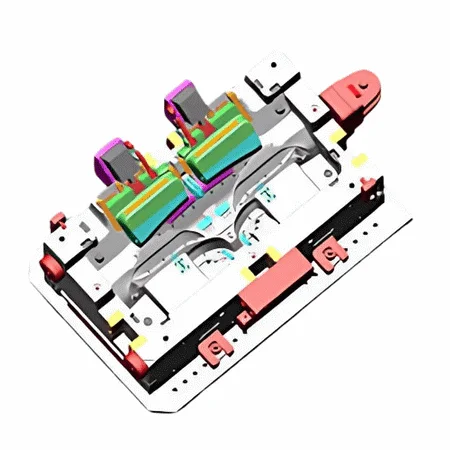
Most injection mold cost surprises are decided before the tool is built.
A design that is technically valid but awkward to mold still gets cut, and the result is a
tool that needs rework, a longer schedule, or a part that warps in production. This
checklist is the set of rules our engineers check on every incoming 3D file, written so
you can run the same review yourself before you submit a quotation request.
Short answer
Before steel is cut, confirm eight things: adequate draft angle,
uniform wall thickness, ribs sized at roughly half the wall,
a parting line placed away from cosmetic surfaces, gate
position matched to the load and appearance, an ejection strategy
that does not mark the part, and tolerances that account for shrinkage.
Parts that satisfy all eight can usually be tooled without design changes.
Each of these is a small change to make in CAD. Each of them caught late becomes a
change to steel.
Why design drives tooling cost
Tooling cost is driven by two things: how much steel is machined, and how many
sub-molds the part requires. Design decisions affect both, and they also decide whether
the tool needs rework after the first trial.
| Design decision | Effect on the tool | Typical cost impact |
|---|---|---|
| Undercut on an outside surface | Requires a slider that moves sideways during the shot | Adds one sub-mold: typically 15-25% of tool price |
| Internal thread | Requires a unscrewing or rotating core | Adds a complex sub-mold: 25-40% of tool price |
| Deep core | Extended core steel, more machining, more draft demand | Moderate, plus higher risk of core breakage |
| Class A or high-gloss surface | Polishing across the full cavity, tighter tolerance on polish | 20-40% of tool price |
| Hot runner | Manifold and valve hardware, more complex runner design | Moderate to high, offset by lower scrap at volume |
| Tight tolerance on a non-critical dimension | More precise machining or a machined pocket insert | Low if designed in, high if requested after cutting |
The mold design guide covers the underlying
principles in more detail, and our mold flow
analysis page explains how a simulation predicts fill, weld line position and
sink before any steel exists.
The design checklist
Here is the full list, in the order our engineers work through it. Each item states the
rule, why it matters, and what happens if it is missed.
| # | Check | Rule of thumb | If it is missed |
|---|---|---|---|
| 1 | Draft angle | 1-3 degrees, increasing along the pull direction | Part will not eject, or steel gets damaged |
| 2 | Wall thickness uniformity | Aim for constant wall; avoid abrupt thick-to-thin steps | Sink marks, warpage, inconsistent shrinkage |
| 3 | Rib thickness | 50-60% of the adjacent wall | Sink marks directly over the rib |
| 4 | Parting line position | On a non-cosmetic face, not across a visible surface | Visible parting line, potential flash |
| 5 | Gate position | Fill from the thickest or most constrained section; keep gates off show faces | Weld lines on show surfaces, uneven packing |
| 6 | Ejection method | Distribute over the part, never on a cosmetic face | Witness marks, deformation of thin parts |
| 7 | Undercuts and sub-molds | Identify every feature that cannot pull straight off | Unexpected cost and lead time, or a design that cannot be built |
| 8 | Tolerance stack-up | Apply shrink allowance, then check the worst-case stack | Part out of tolerance and cannot be corrected |
Draft and wall thickness
Draft is the angle that lets the part separate from the steel. It is not a cosmetic
detail, it is what makes ejection physically possible.
- Polished surfaces need less draft than textured ones. A polished
cavity surface is easier to release against, so 1 degree can work. A textured surface
mechanically grips the part, so 2 to 3 degrees is the safer starting point. - Draft must increase along the pull direction, not just exist at the opening.
A constant 1-degree wall on a 200 mm deep part still drags near the base. - Keep wall thickness as uniform as possible. Thick sections cool and
shrink far more than thin ones, so a thick-to-thin transition is the main cause of
warpage in an otherwise sound design. - Use ribs to add stiffness instead of thickening the wall. A rib at
55% of the wall thickness delivers more stiffness per unit of shrink than a thicker wall,
and shrinks like the wall it sits on. - Add corner radii. A sharp internal corner concentrates material and
acts as a stress raiser; a radius of roughly half the wall thickness lets the flow turn
without a thin spot.
Gates, parting lines and ejection
These three decisions interact, so they are best reviewed together rather than one at
a time.
Gate position determines where the material enters and therefore where
the weld line forms. Weld lines are weak and, on a visible surface, they show. A gate
placed on a show face, or positioned so that the weld line lands where the customer
looks, is a design problem rather than a tooling problem. For most cosmetic parts the
gate goes on a hidden face, and for critical surfaces a valve-gate hot runner is worth
the tooling cost.
Parting line is where the two halves of the tool meet. It exists
somewhere on every part, so the design question is where to put it. The best location is
a surface the customer does not look at, aligned with a natural geometric feature such
as a corner or a step. The worst location is a large flat show face.
Ejection is how the part is pushed off the core. Pushers work on
rigid, well-supported parts but mark them if they land on a cosmetic surface or on a
thin wall. Strippers work well for shallow, thin parts but leave a witness mark. For
transparent or high-gloss parts, air-assisted ejection or a low-profile ejector layout is
usually worth specifying. Our injection molding
process page covers how each phase of the shot interacts with these decisions.
Tolerances and shrinkage
Every plastic shrinks as it cools, by an amount that depends on the resin, the
moulding conditions and the part’s geometry. The mold is cut to the shrunk dimension, so
if the shrink allowance is wrong, every part is out of tolerance.
| Material family | Typical shrink range | Design note |
|---|---|---|
| PP (polypropylene) | 1.5-2.5% | High shrink, needs generous allowance and steady cooling |
| ABS / ABS-PC | 0.5-0.8% | Stable and predictable; tight tolerances are achievable |
| PC (polycarbonate) | 0.5-0.7% | Requires thorough drying before moulding |
| PA6 / PA66 (nylon) | 0.8-2.0% | Hygroscopic, so conditions shift part to part |
| POM (acetal) | 1.8-2.5% | High shrink and sensitive to flow history |
| PS / HIPS | 0.3-0.6% | Low shrink, good dimensional stability |
Two practical points. First, apply the shrink allowance to the flow direction
differently from the cross-flow direction, because most materials shrink more along the
flow path than across it. Second, tolerances stack, so a part with eight nominally
tighter dimensions in series may not be buildable even when each one is achievable on
its own. A tolerance that no one will measure on a critical function is a good place to
save money.
What a DFM review covers
This is what our engineering team does when a 3D file arrives, and it is included in
every quotation at no charge:
- Geometry and draft review against the rules above, with specific
values rather than a general opinion. - Mold flow simulation showing fill pattern, weld line position, air
trapping and expected sink locations. - Wall and rib analysis, identifying non-uniform sections and proposing
a rib layout instead of a thicker wall. - Parting line and gate proposal, with the reasoning for why each was
chosen. - Tolerance feasibility, including shrink allowance and stack-up.
- Risk flags for anything that could cause warpage or flash, and
specific changes that remove the risk.
The review comes back within 24 hours of receiving your files, with a written
recommendation. If a change we propose adds cost, we say so and quantify it, so you can
decide whether the performance is worth it. Our quality and
certifications page lists the inspection and documentation included with first-article
approval.
Send your STEP or IGS files with the target material and annual volume, and the team
will tell you what is achievable on your geometry before you commit to tooling.
What real design reviews look like
The checklist above is general. Here is how it plays out on four geometries that come
through our DFM review most often, and what each one actually needed.
Scenario 1: A consumer electronics enclosure with an internal snap fit
A 160 mm ABS housing with a cosmetic lid surface and a cantilever snap on the side.
The submitted file had 0.6 mm walls and a snap feature that released against a
zero-draft surface. Two changes fixed it: walls to 1.2 mm with ribs at 0.7 mm instead of
a thicker shell, and 2 degrees of draft added to the snap. Neither change altered the
external appearance or any functional dimension. Tooling impact: none.
Cost avoided: a tool that would have dragged on every cycle and needed rework after
the first trial.
Scenario 2: An automotive clip with a side hole
A 90 mm PA6 clip with a 6 mm hole running sideways through a boss. The hole could not
be pulled straight off the core, so it needed a slider. The review proposed moving the
hole 4 mm and rotating it 90 degrees so it became a straightforward through-hole on the
core, which removed the sub-mold entirely. Tooling impact: roughly USD 6,000
of sub-mold cost avoided, and the lead time dropped by about two weeks. The
customer kept the same external fixing geometry.
Scenario 3: A medical housing with a 0.15 mm tolerance on a sealing face
PC/ABS, single cavity, S136 steel, with a sealing face specified at +/-0.15 mm and a
general tolerance of +/-0.3 mm elsewhere. Simulation showed the packing around the gate
could not hold 0.15 mm consistently, so the review recommended a machined pocket insert
on that face rather than tightening the whole cavity. Tooling impact: one
insert instead of a full cavity rework, and the tolerance became something the
process could actually hold repeatably rather than something that passed on the first
article and drifted afterwards.
Scenario 4: A high-volume cap that warped in trial
PP, 250,000 parts a year, with a thin wall on one side and a thick boss on the
other. The trial parts warped because the two sections shrank at different rates. The
design was sound in the CAD sense, but the simulation flagged it. The fix was
redistributing material rather than changing dimensions: a thinner wall with ribs, and
the boss wall brought down toward the nominal wall thickness. Tooling impact:
none, because the correction was made in the file before the tool was cut
rather than in the process window afterwards.
Design and tooling terms quick reference
| Term | Meaning | Why it matters at design stage |
|---|---|---|
| Draft angle | Taper on a surface parallel to the pull direction | Without it the part cannot be ejected |
| Parting line | The line where the two tool halves meet | Its position is a design choice, not a tooling one |
| Undercut | A feature that blocks straight-line withdrawal | Each undercut needs a sub-mold |
| Sub-mold | A separate moving insert: slider, lifter, unscrewing core | Adds 15-40% to tool price and 1-2 weeks |
| Shrink allowance | The dimension the cavity is cut oversize by | Get it wrong and every part is out of tolerance |
| Weld line | Seam where two melt fronts re-join | Set by gate position; weak and visible on show surfaces |
| Sink mark | Local depression over a thick section | Caused by excessive local shrink; fix by ribbing, not by pressure |
| Short shot | Part that did not fill completely | Usually a gate or venting problem, but often a wall thickness one |
| Flash | Thin excess material at the parting line | Indicates the parting line is not sealing: alignment or venting |
| First article | The first production part, inspected against the drawing | The point where tolerance problems surface; confirm what the report covers |
Frequently Asked Questions
What is an injection mold design checklist?
How much draft angle does an injection molded part need?
What is the minimum wall thickness for injection molding?
Why do ribs need to be half the wall thickness?
How do I know if my design needs a slider or lifter?
Do you review designs before quoting, and is it free?
Where this applies
Send us your 3D files for a DFM-backed quote
Share your STEP or IGS files with target volume and material. Most quotes are returned within 24 hours.
- 23+ Years of experience
- 2,000+ Molds per year
- 24h Quote turnaround