
Injection Mold Maintenance: Tool Life, Schedules and Common Failures
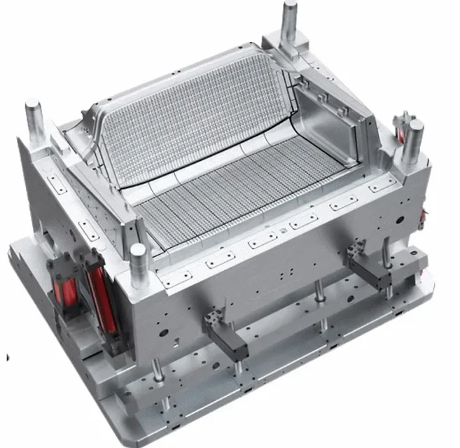
Every injection mold has a life, and almost nobody finds out what that life is until the tool starts failing. The published number for a pre-hardened tool is somewhere between 200,000 and 500,000 shots, but the gap between that number and the shots your tool actually delivers is where most of the cost hides. That gap is not mysterious — it is wear that was never measured, because nobody agreed who was going to measure it. This guide sets out what limits tool life, what a realistic maintenance schedule looks like, and which wear parts end a tool’s life first.
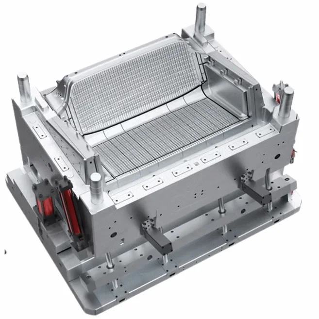
Three factors decide how long a tool lasts
A production tool is not a single object with a single expiry date. It is a steel frame with a set of replaceable wear components, and the tool’s useful life is governed by the weakest component that is expensive to replace — usually the cavity steel surface, the slide cores, or the ejector system. A mold can be perfectly serviceable at 400,000 shots if the wear parts were changed on time and unusable at 80,000 if they were not.
Three factors decide the number, and it is worth keeping them separate because each one is fixed by a different decision made at a different time:
- The steel. This is the ceiling and it is decided when the tool is quoted, when somebody chooses between P20, 718H, H13, S136 and NAK80. It cannot be improved later without rebuilding the tool.
- The material being moulded. Glass and mineral fibre are abrasive, and they cut tool life by roughly a factor of four compared with unfilled resin. A tool designed for unfilled ABS is not a tool designed for 30 percent glass fibre, and quoting it that way is one of the most common and most expensive specification errors in the industry.
- The maintenance regime. This is the only one of the three that can be changed on any given day, without money and without steel. A disciplined programme typically recovers 30 to 50 percent of the theoretical shot count, and often more than that.
There is a fourth factor that is easy to forget: how the tool is stored and how it is restarted. A mold that is stored wet, or restarted without a controlled procedure, can lose a quarter of its remaining life before it makes a single good part. Our mold maintenance page covers the practical procedures, and this guide covers the reasoning behind them so you can build a schedule that fits your own volume rather than copying someone else’s.
What actually limits tool life
It is tempting to treat tool life as a single number, but a tool fails through several distinct mechanisms, and they do not all arrive together.
Surface wear on the cavity steel is the slow one. Resin flowing across the cavity under pressure slowly polishes and then abrades the steel. The practical symptom is a gradual drift: flash appearing on the parting line, the part gaining weight, dimensions moving off nominal. It is hard to see early because each shot is nearly identical, and by the time it is obvious the tool has already been running out of tolerance for a while.
Wear-part failure is the fast one, and it is also the cheapest to prevent. Ejector pins wear at the tip, sprue bushings wear at the bore, gate inserts wear at the gate lip, slide gibs wear on the bearing face. Each of these has a defined replacement cycle, and each failure is usually visible well before it happens — a pin that is nearly worn leaves a mark, a bushing that is nearly worn changes the sprue.
Fatigue and thermal damage is the slow one that is specific to the tool. Cooling channels work by cycling the tool steel between cold and hot thousands of times a day. Core pins that are under-modelled, or that have no cooling at all, eventually crack at the root. This failure is not gradual and it is not caused by resin; it is caused by the thermal design of the tool, which is why it is the failure mode that most reliably traces back to a decision made at design review.
Damage from the outside — a dropped tool, a bad ejection, a forced insert, a misaligned machine — is the most expensive category and the least predictable. A single bad shutdown can cost more than five years of planned maintenance. It is also the category most sensitive to the handling procedures in your turnkey arrangement, because a tool that lives at the molder’s site is handled by people whose only job is to run it.
Understanding which mechanism you are dealing with matters, because the responses are completely different. Surface wear is a scheduling question. Wear-part failure is a stocking question. Thermal fatigue is a design question, and the answer is a different tool, not a better-maintained one.
Expected tool life by steel and material
The table below gives realistic shot counts for a well-designed, correctly maintained tool. The wide ranges are not hedging — they reflect real variation between a tool with good cooling and one with poor cooling, and between a part with a light section and a heavily ribbed one.
| Steel | Typical hardness | Unfilled resin | 30% glass fibre | Typical use |
|---|---|---|---|---|
| P20 | 28-34 HRC (pre-hardened) | 200,000 – 500,000 shots | 40,000 – 120,000 shots | General purpose, short-to-medium runs |
| 718H | 32-38 HRC (pre-hardened) | 300,000 – 800,000 shots | 80,000 – 200,000 shots | High polish, cosmetic parts |
| H13 | 44-50 HRC (hardened) | 800,000 – 2,000,000 shots | 200,000 – 500,000 shots | High volume, hot runners, high pressure |
| S136 | 48-52 HRC (stainless, hardened) | 600,000 – 1,500,000 shots | 150,000 – 400,000 shots | Medical, food, corrosion resistance |
| NAK80 | 37-42 HRC (age-hardened) | 1,000,000 – 2,500,000 shots | 250,000 – 600,000 shots | Very high volume, no heat treatment |
Two caveats that matter more than the numbers. First, these are shot counts for the tool, not for the part — a four-cavity tool produces four parts per shot, so it reaches its shot limit four times faster in parts than it does in cycles, and the tool needs to be dimensionally capable of four parts at once, which is a harder requirement. Second, the abrasive column is not linear: the jump from unfilled to 30 percent glass fibre is severe, but the jump from 30 to 50 percent is much less severe than the first, because the fibre is already the dominant wear mechanism by then.
The point of specifying the steel properly is on our mold steel selection guide. Two tools built for the same part in different materials should not have the same steel, and the correct choice for a glass-filled part is usually not the cheapest one. Our mold design guide covers where cooling and rib design affect which of these limits you hit first.
A maintenance schedule that scales with volume
A maintenance schedule should be derived from shot rate, not copied from a catalogue. A tool running 5,000 shots a year needs an annual inspection and nothing more. A tool running 5,000 shots a day needs a daily check and a quarterly teardown, and anything less is not a maintenance programme, it is a hope.
| Interval | Low volume (under 50k shots/yr) | Medium volume (50k – 500k shots/yr) | High volume (over 500k shots/yr) |
|---|---|---|---|
| Every shift | Wipe cavity and parting line, check for flash and short shots | As low volume, plus log cavity and melt temperature | As medium volume, plus check vent condition and cooling flow |
| Weekly | Check vent condition, lubricate ejector system | Weekly checks plus inspect ejector pin tips and bushings | Weekly checks plus lubricate and inspect all slides and gibs |
| Monthly | Not required | Verify cooling flow and temperatures across circuits | Monthly checks plus water filter and cooling circuit condition |
| Quarterly | Full clean, spot-check key dimensions | Full teardown inspection, measure wear parts against limits | Quarterly teardown plus replace wear parts at limit |
| Every 50k – 100k shots | Not required | Strip down, clean cooling channels, replace worn pins and springs | Strip down, clean channels, replace all wear parts at limit, check cavity polish |
| Annually | CMM check of critical dimensions | CMM check plus cavity polish assessment | CMM check plus polish restoration and full dimensional report |
Two rules make this work in practice. The first is that wear parts are replaced on measurement, not on the calendar — the interval tells you when to look, the measurement tells you when to change. A tool on a difficult glass-filled programme will consume pins three times faster than the schedule assumes, and a calendar-driven programme will replace good pins early on one tool and miss worn ones on another.
The second is that the shot count must be recorded per cavity, not per tool. Once one cavity of a four-cavity tool starts running behind, the tool still produces four parts per cycle but the good cavities are doing more work, and the tool’s life is now limited by the worst cavity. This is why quality control and maintenance are the same conversation: the first-article measurement is also the baseline you measure wear against.
The wear parts that end tool life
These are the components that are designed to be replaced. Quoting a tool without identifying them is like quoting a car without a service schedule — the numbers cannot be interpreted without them.
| Wear part | What it does | Life (unfilled) | Life (30% GF) | Early warning sign |
|---|---|---|---|---|
| Ejector pins and sleeves | Push the part off the core | 100,000 – 300,000 shots | 30,000 – 80,000 shots | White marks or witness lines on the part |
| Sprue bushing | Forms the sprue and seats the nozzle | 150,000 – 400,000 shots | 50,000 – 120,000 shots | Sprue diameter drifting, nozzle not seating |
| Gate inserts | Form the gate into the cavity | 200,000 – 600,000 shots | 60,000 – 150,000 shots | Gate lip rounding, visible gate witness |
| Slide cores and gibs | Form undercuts, retract before opening | 300,000 – 800,000 shots | 100,000 – 250,000 shots | Part dragging on one side, gib shine marks |
| Return pins and bushings | Locate the two halves on closing | 500,000 – 1,000,000 shots | 150,000 – 400,000 shots | Parting line mismatch, uneven flash |
| Cooling fittings and seals | Seal the coolant circuit | 100,000 – 250,000 shots | 80,000 – 200,000 shots | Coolant weeping, temperature drift on a circuit |
| O-rings and seals | Seal the nozzle and the mould | 50,000 – 150,000 shots | 40,000 – 100,000 shots | Nozzle drool, visible compression set |
Every one of those items is a cheap, standard, stocked part. The expensive part is the downtime: a tool that is down for a pin change is a tool that is not making parts, and in a just-in-time supply chain that outage moves down the line. The practical way to protect against that is to hold the wear parts yourself — the seven rows above are the entire list, and it is a short list. Our factory and equipment page shows how we keep wear parts in stock for the tools running in our own production cells.
There is also a version of this that matters if the tool ships to you rather than staying with us. In that case the question of who holds the spares is worth settling in the contract, because a customer who cannot source a sprue bushing in four days has a problem that no maintenance schedule solves.
Warning signs that a tool is degrading
The most useful diagnostic question is not “what defect is this” but “is the behaviour changing or repeating”. Wear produces a trend. A material lot or a machine fault produces a shift. That distinction saves an enormous number of unnecessary tool modifications.
| Symptom | Most likely cause | Check this first | Action |
|---|---|---|---|
| Flash growing on one cavity only | Cavity wear or parting line damage | Compare the cavity against a known-good one | Measure, then repair the cavity — not the clamp force |
| Part weight drifting upward | Gate or sprue wear | Weigh 10 parts and compare with the first-article weight | Replace the gate insert or sprue bushing |
| Sink marks deepening or moving | Cooling imbalance, or wear changing the thermal picture | Mould temperature on each side of the part | Verify cooling, then re-assess the design |
| Ejection marks after a cleaning cycle | Ejector pin wear or a bent pin | Inspect pin tips under magnification | Replace the pin set, check alignment |
| Scrap rate rising on the same material | Tool wear, or a resin lot change | Check whether the trend is gradual or sudden | Gradual means wear; sudden means material |
| Cycle time creeping up | Cooling fouling or scale in the channels | Compare tool surface temperature to the set window | Strip and clean the cooling circuits |
| Short shots on start-up only | Cold tool, not wear | Tool temperature at first shot | Run the defined warm-up procedure |
| Same defect appearing and disappearing within a shift | Process or material, not wear | Check the resin drying and feeder | Do not modify the tool |
The last row is the one that saves the most money. A tool that is wearing down does not behave intermittently — it behaves consistently, and it gets steadily worse. Intermittent behaviour under constant settings is almost always resin moisture, a nozzle problem, or a feeder problem. Our injection molding defects reference covers each defect’s geometry, process and material causes in detail, and the moulding process guide sets out the order in which parameters should be changed so that you can isolate a cause rather than chase several at once.
Storage, restart and the cost of neglect
Storage is where a large amount of tool value quietly disappears, and it is the one part of tool ownership that is entirely under your control and costs nothing to do properly.
The mechanism is simple. Steel rusts when it is wet and when there is oxygen. A mold that is put away with residual coolant, resin or cleaning water inside it will show rust within weeks. And rust on a working surface is not a cleaning job — it is a cavity repair, because the surface has to be cut or polished back to specification, and that changes the part. A cavity that was polished to SPI A1 and came back from storage with a repaired surface will produce visible parts and possibly out-of-tolerance dimensions.
The procedure that prevents this is not complicated: dry the tool completely, apply a corrosion-inhibiting coating, close and seal it, include desiccant, and store it off the floor in a room with controlled humidity. What goes with the tool matters just as much as the tool itself — the last trial report, the maintenance log and the spare parts list. A tool that returns to the press with its own history attached can be restarted properly; a bare tool cannot.
The restart procedure is the part people skip. After storage, before the first production shot, the tool should be re-checked: inspect the parting line and cavity surfaces for rust, re-grease slides and check gib engagement, re-tension the ejector system, verify the cooling circuit is clean and the seals are sound, and confirm the nozzle is centred. Then run a controlled trial with full parameter logging and measure the first article against the drawing. Our process guide covers how to set that trial up, and the T0 and T1 convention gives you a clean baseline to compare against.
What to log so the next tool is cheaper
The single highest-value item in this entire guide costs nothing: keep the tool’s records with the tool. Four things, and every one of them makes the next tool better.
- Shot count per cavity. This is what tells you the real life rather than the rated life, and it is what tells you when to look at a cavity that is falling behind the others.
- The maintenance log, with measurements. A log that records what was replaced, when, and how worn it was, is the difference between knowing the tool’s condition and guessing at it. Our toolroom keeps the log per tool serial number, and it travels with the tool when it is stored or shipped.
- The first-article report and the last trial report. These are the baseline for any dimensional question you will ask about that part for the next five years. Without them, every dimensional dispute is settled by opinion.
- The wear parts list with quantities. Identify the wear items at tool handover — ejector pins, slide plates, gate inserts, O-rings, bushings — and hand over the part numbers. A tool that comes with a spare parts list and a defined restart procedure is a tool whose owner can protect it.
Our quality and certifications page describes the documentation package we issue with every tool, including mill certificates with heat-lot traceability, the CMM dimensional report, the trial report with parameter logs and the first-article inspection report. That package is not paperwork for its own sake — it is the material you need to run the maintenance schedule, and the material you need if the tool is ever moved to a different molder.
What maintenance actually costs
Two numbers settle this argument, and both are worth putting in your own business case before anyone asks.
The cost of unplanned downtime. A tool down for a day on a programme running 5,000 shots a week is roughly 1,400 lost shots, plus the overtime or the alternative source needed to keep the line running. For a tool running 50,000 shots a year, planned maintenance at the same level costs a small fraction of a single unplanned breakdown. Maintenance is not a cost centre; it is insurance against a much larger and much less predictable cost.
The cost of a short life. If your tool is reaching a third of its rated life because the wear parts were never replaced, the difference between the rated life and the achieved life is being paid for at the rate of a whole new tool every year. That is the comparison that makes the business case: not “what does maintenance cost” but “what does the gap between rated and achieved life cost”.
There is a third option worth naming, because it is sometimes the right answer. For a low-volume tool that will only ever run a few thousand shots, a planned teardown may never pay for itself. In that case the sensible strategy is a simple tool designed to be disposable rather than an expensive tool maintained forever. Our injection mold cost breakdown covers the cost structure that decision sits inside, and the twelve questions that qualify a mould maker covers what to ask about maintenance support before you award the order.
Three toolroom decisions
A maintenance schedule is only as good as the judgement behind it, and the judgement is usually tested by a decision that has to be made with incomplete information. These three are real decisions from our own toolroom, and in each case the answer that seemed obvious was wrong, because the tool was being read as worn when it was not, or as fine when it was not.
Case 1: The tool that was “worn out” after 60,000 shots
A medical device customer reported that their P20 tool was reaching the end of its useful life and asked us to quote a replacement. The tool was a glass-filled part, and 60,000 shots against a rated life of several hundred thousand looked like wear.
Before quoting, we asked for the wear part measurements from the last teardown. The ejector pins were at 40 percent of their limit, the sprue bushing at 30 percent, and the cavity surface was still showing original polish. The tool was not worn. What had happened was that the pin set had been replaced with pins from a different hardness grade during a rush repair, and the difference in hardness was eating the ejector bores rather than the pins. We changed the spare part specification, put the replacement pins on a documented cycle, and the tool went back to running. The general lesson is that a shot count on its own tells you very little, because the same shot count can mean completely different things depending on the resin, the wear part grade and the tool geometry. Measure the wear parts before you conclude the tool is finished.
Case 2: The intermittent flash that was actually a nozzle
An appliance customer reported flash appearing on roughly one shot in sixty on a large housing, never on the first two hours of a shift. The obvious reading was that the tool was closing unevenly, and the obvious fix was to re-machine the parting line.
We weighed the tool before touching it, and the parting line measured clean on all four corners. The flash was not at the parting line at all — it was a ring around the sprue, which pointed at the nozzle rather than the tool. The nozzle was a cold runner nozzle with a worn tip, and it was not seating properly against the sprue bushing, letting material escape. It was replaced with a new nozzle and a re-torqued sprue bushing, and the flash stopped immediately, for the cost of one part. The general lesson is that flash has several distinct causes, and the cheapest diagnostic is establishing where the flash is before deciding what it means. A parting line that measures clean is a very strong signal that the tool is not the problem, and re-machining it would have cost thousands and changed nothing. Our injection molding defects reference covers the geometry causes in full.
Case 3: The tool that came back from storage with a cavity repair
A customer stored a cosmetic tool over a long shutdown and returned it to us for a restart. The tool had been closed and bagged but was never dried, and the residual coolant had enough moisture in it to put a light surface rust across the cavity. The customer wanted us to polish it back and run it.
We did not, because polishing rust out of a cosmetic cavity changes the surface texture and the customer had a colour and gloss specification. The correct treatment was to cut the cavity back and re-polish to the original specification, which is a proper cavity repair and not a cleaning job, and we quoted it as one. The tool went back into production on the repaired cavity with a documented specification, and the customer was given the drying, coating and desiccant procedure to use next time. The general lesson is that storage is not free and it is not a break in the tool’s life either — a tool stored wet does not get a bit tired, it gets a cavity repair, and that is one of the most expensive items on any tool. Our mold maintenance page sets out the storage and restart procedures that prevent it.
Tool care and tool life terms quick reference
| Term | Meaning | Why it matters when running or buying a tool |
|---|---|---|
| Shot count | The number of moulding cycles a tool or cavity has completed | The starting point for every maintenance interval; recorded per cavity, because the worst cavity sets the limit |
| Wear part | A component designed to wear and be replaced, rather than to last the life of the tool | Identifying the wear parts and their limits is what makes a maintenance schedule possible |
| Ejector pin | The pin that pushes the part off the core | The most frequently replaced wear part; a worn pin leaves marks on the part before it fails |
| Sprue bushing | The insert that forms the sprue and seats the machine nozzle | Its wear changes the sprue diameter and shows up as a drifting part weight |
| Gate insert | The insert that forms the gate into the cavity | A rounded gate lip changes both the gate appearance and the fill pattern |
| Slide and gib | A moving core that forms an undercut, and the guide it runs on | Gib wear shows as drag marks on one side of the part, not as a sudden failure |
| Return pin | The pin that locates the two halves of the tool on closing | Worn return pins allow parting line mismatch and uneven flash |
| Parting line | The line where the two halves of the tool meet | Flash location tells you where to look; a clean parting line measurement rules the tool out |
| Core | The male half of the cavity, which forms the internal features of the part | Cooling the core is what controls the internal dimensions and the warpage |
| Cavity | The female half of the tool, which forms the external features of the part | Cavity polish and cavity wear set both the surface quality and the flash behaviour |
| Hot runner | A heated manifold that keeps the melt hot all the way to the cavity | Removes runner scrap and cold slugging; needs more control and more maintenance |
| Tear-down | Pulling the tool apart for cleaning, inspection and wear part replacement | The interval that separates a tool reaching its rated life from one failing at a third of it |
| Desiccant | A moisture-absorbing material used in sealed tool storage | Together with drying and coating, it is what prevents a stored tool from needing a cavity repair |
| First article | The first production part, inspected in full against the drawing | Also the baseline every future wear measurement is compared against |
Tool life and maintenance questions, answered
How long does an injection mold actually last?
What does injection mold maintenance actually involve?
How often should I replace mold wear parts?
What are the warning signs that a mold is degrading?
Can a worn mold be repaired instead of replaced?
How should a mold be stored between projects?
Does mold maintenance cost more than building a better mold?
Who should own the maintenance schedule?
The tooling services that protect your tool life
Send us the drawing and we will tell you the tool life
Share the STEP or IGS file, the material grade and the annual volume. We will tell you which steel the tool needs, what its realistic shot life is, and what the maintenance schedule should look like for that volume.
No obligation. NDA available.
- 23+ Years of experience
- 2,000+ Molds per year
- 24h Quote turnaround